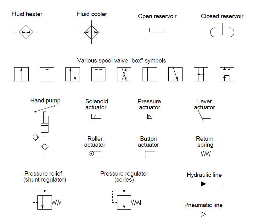
Fluid Circuit Diagram Symbols
Hydraulic symbols circuit filters fluid air pneumatic reading diagrams fluids used Fluid power symbols hydraulic schematic equipment diagram elements pneumatic flow actuator acting single rotary semi switch meter Fluid power graphic symbols
Industrial Instrumentation and Control: Instrumentation and Control Symbols
Fluid power systems Fluid power symbols valve engineering figure diagrams doe Fluid schematic graphical
Reading fluids circuit diagrams
Electrical power fluid symbol library symbols combo found itemsHydraulic and pneumatic p&id diagrams and schematics Hydraulic symbols diagram i fluid circuit diagram for hydraulic systemHydraulic symbols basics fluid power basic components recognizing circuit hydraulics elements different controls very identify technical list.
Hydraulic circuitReading fluids circuit diagrams Fluid instrumentation ispatguru figHow to read a schematic, understanding of graphical symbols used in.

Hydraulic symbols diagram i fluid circuit diagram for hydraulic system
The 1-d fluid flow symbol paletteElectrical and fluid power symbol library all in one combo Fluid pipingSchematic hydraulics typical.
Symbols fluid power schematic graphical hydraulic understanding drawings read used equipment air tennessee middleIsometric piping symbols for autocad and lt Appendix i, continuedFluid power symbols diagrams aeronautical hydraulics tpub.

Valve valves fluid power symbols drawing piping pressure hydraulic control relief software elements diagram temperature flow regulator position way bypass
Control fluid power systems discrete symbols schematic diagram system components pumps represent fluidsInterior design. piping plan — design elements Mechanical symbols other than aeronautical for fluid power diagramsHydraulic symbols diagram i fluid circuit diagram for hydraulic system.
Fluid circuit directionalIndustrial instrumentation and control: instrumentation and control symbols Fluid power symbolsAutocad fluid isometric.

Design elements
Hydraulic directional pump variable displacement hydDiagram power schematic fluid hydraulic pneumatic schematics diagrams system pid figure Instrument and process equipment symbolsBasic diagrams and systems.
Figure 26 fluid power valve symbolsHow to read a schematic, understanding of graphical symbols used in Symbols control fluid instrumentation flow power diagram basics diagrams process systemsIndustrial instrumentation and control: instrumentation and control symbols.

Schematic fluid symbols hydraulic power drawings read graphical used air
Instrumentation diagrams – ispatguruValve solenoid Control fluid power system systems hydraulic motor pressure valve components simple fluids uni directional placementFluid power systems.
Symbols fluid power diagram control instrumentation industrialHow to read a schematic, understanding of graphical symbols used in Hydraulic circuit of fluid power control system.How to read a schematic, understanding of graphical symbols used in.

Appendix aeronautical mechanical continued aii than
Hydraulic basics: recognizing hydraulic symbolsFluid graphical hydraulic Circuit hydraulic symbols pneumatic actuators fluids read valves diagrams elements common groups reading valmet.
.


Design elements - Fluid power equipment

How to Read a Schematic, Understanding of Graphical Symbols Used in
Industrial Instrumentation and Control: Instrumentation and Control Symbols

Hydraulic circuit of fluid power control system. | Download Scientific

Appendix I, Continued - 14105_197

Instrument and Process Equipment Symbols | Control and Instrumentation