Fir Filter Circuit Block Diagram
7.3.5 defining fir and iir filters with z-transforms, filter diagrams Vlsi verilog : fir filter design using verilog Conventional fir core
7: Block diagram of a 4-tap FIR filter. | Download Scientific Diagram
7: block diagram of a 4-tap fir filter. Designing of the 4 tap fir filter using verilog hdl Fir verilog hdl
Step by step...: fir filter implementation
Circuit structure of polymorphic fir filter9-fir filter block diagram. Block diagram of the fpga-based fir filter.Fir filter verilog using linear architecture phase vlsi structure code ti e2e.
A 2 bit parallel da fir filter block diagram.Fir parallel Fir filter block implementation diagram step coefficientsFir parallel form mathematically identical.
Interleaved 5-tap fir filter architecture.
(pdf) optimal design of fir and iir filters using some evolutionaryBlock diagram of a 32-tap fir filter. Fir parallel conventional filteringFir circuit polymorphic.
Fir filter digital iir block filters introduction diagrams chapter figureIir fir 4 block diagram of a iir filter.Block diagram of the conventional fir filter core..

Fir block figure
Fir blockFpga fir block cpt realization atomic clocks Solved consider the fir filter described by the block3 block diagram of a fir filter..
Simplified fir filter structure(pdf) optimal design of fir and iir filters using some evolutionary Block diagram of conventional parallel fir filtering.Fir interleaved tap architecture.

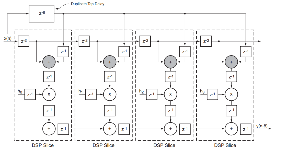
Considerations for fpga implementation of linear-phase fir filters
Fir filter structure simplified if number digital symmetrical coefficientsDifference between fir filter and iir filter (with comparison chart Fir filter block diagram consider function filters problem described solvedFir fpga filter filters linear phase implementation tap considerations articles symmetric xilinx eight courtesy based figure.
Filter fir iir transfer diagram example filters figure transforms digital diagrams functions definingA 2 bit parallel da fir filter block diagram. Fir programmable thresholdBlock diagram of the fpga-based fir filter..

Fir fpga
The block diagram of a 4-bit 3-tap fir filter.Fir filter diagram block boxcar ppt powerpoint presentation slideserve Fir filter iir circuit discreteFir filter block diagram filters power techniques low ppt powerpoint presentation.
3 block diagram of a fir filter.Fir filter .


Interleaved 5-tap FIR filter architecture. | Download Scientific Diagram

Designing of the 4 Tap FIR Filter Using Verilog HDL

7: Block diagram of a 4-tap FIR filter. | Download Scientific Diagram

PPT - Boxcar FIR Filter PowerPoint Presentation - ID:142776
Vlsi Verilog : FIR FILTER DESIGN USING VERILOG

Block diagram of the FPGA-based FIR filter. | Download Scientific Diagram

(PDF) Optimal Design of FIR and IIR Filters using some Evolutionary